Thursday, April 3, 2014

AutoSprink - 3D Approach to Fire Sprinkler Design

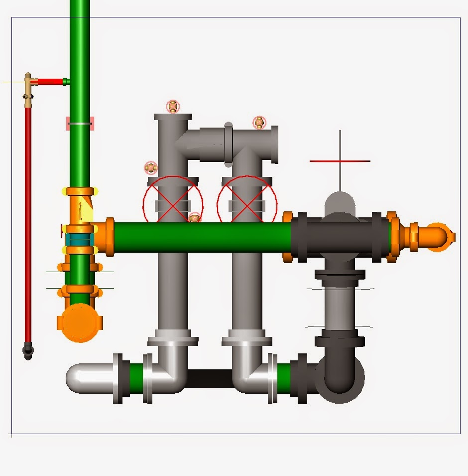
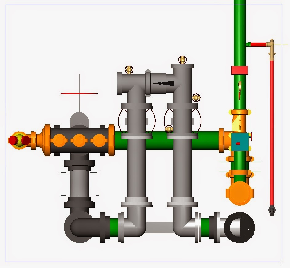
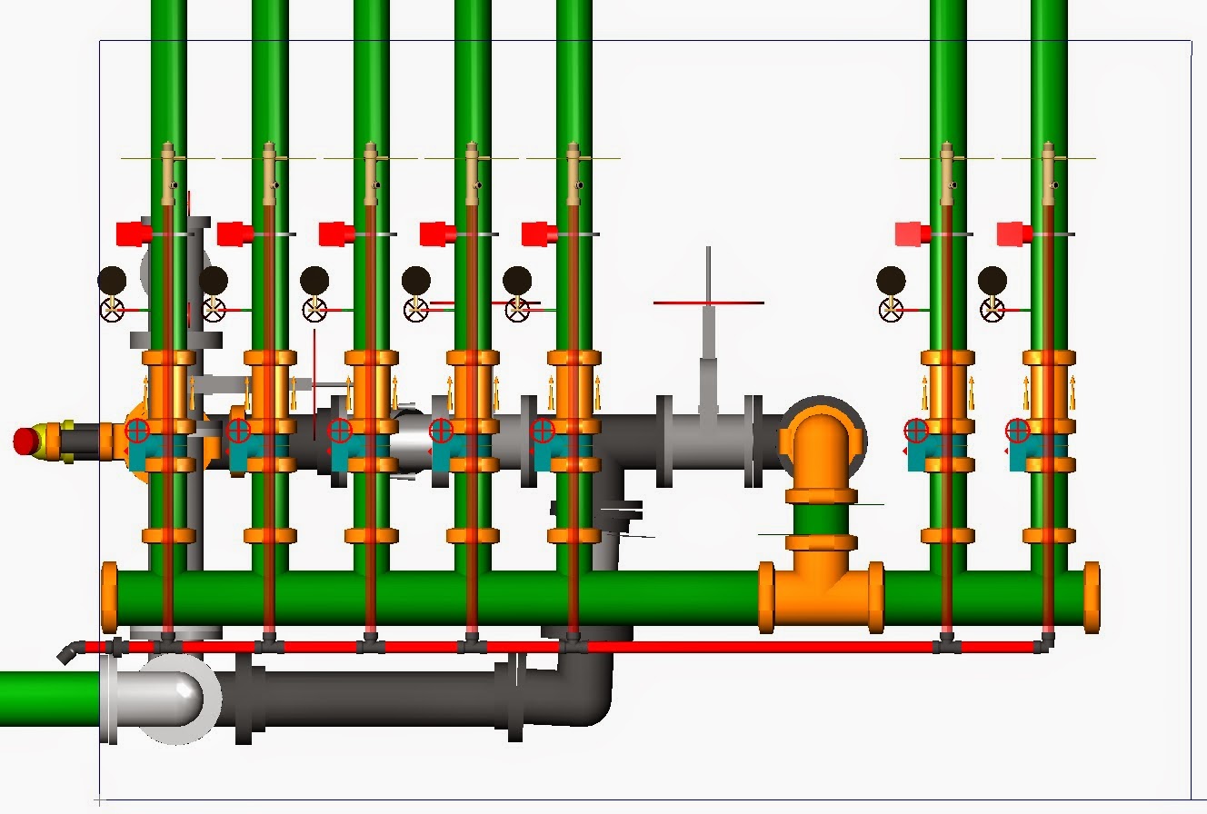
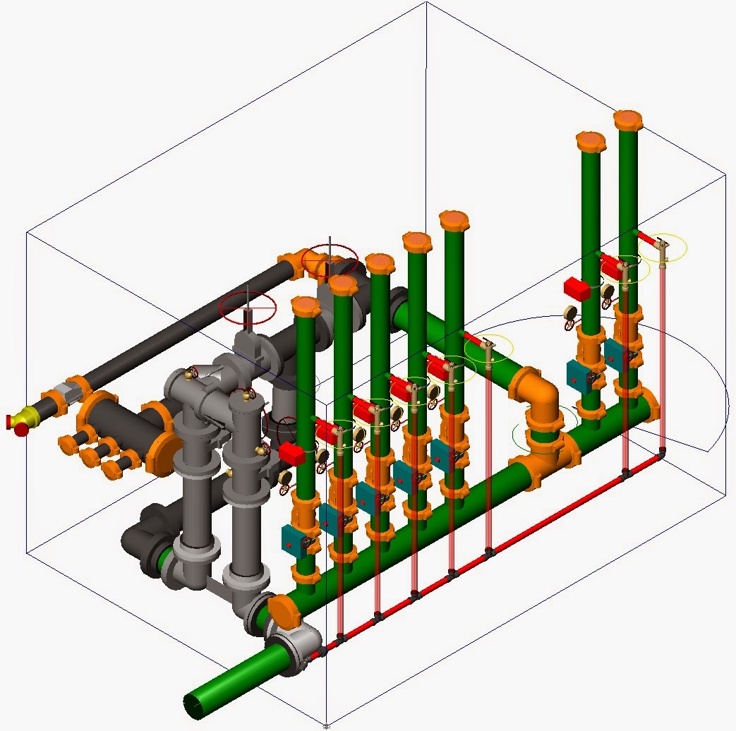
For Fire Sprinkler designs, it is useful to have a 3D view to see what's going on.  Yes, it does take longer, but it may just be worth it in the end (cost/benefit analysis).  Besides, it's nice to be able to show someone what things look like in 3D.  It's one thing to hand someone a set of plans.  It's quite another to show someone a picture.  The drawings below were done using AutoSprink, one of the useful tools available in the industry.

Riser Room - SE Isometric View
 
Riser Room - NW Isometric View
 
North View                                       South View

East View                                     West View
 
Warehouse Sprinkler System Isometric View
 
Health Club Sprinkler System Isometric View
 

Oversized Stair Pressurization Fan


On this particular project the stair pressurization fans for the smoke control system were oversized. Since the fans were direct drive and not on variable frequency drives (VFDs), they could not be slowed down. The only other alternative was to install sheet metal to limit the airflow going into the stairwell.
Having oversized fans creates another interesting challenge - fan status. In order to verify if a fan is running, stopped or is missing a belt (trouble), either a differential pressure switch (DPS) or current transducer switch (CT) is installed.  The DPS measures pressure created by using sensors.  The CT measures electrical current.  There are pros and cons to both, but usually CTs are preferred, mainly because a DPS can give a false reading if there is a wind gust. 
In this case, CTs were used.  However, since the fan motors were oversized, the difference in current between belts off and fan running was only about 0.1 amps, and it took several adjustments to get an accurate reading of fan status – when on normal building power.  When the emergency generator was activated, the current readings shifted because the output voltage of the generator was slightly less than the normal building power.  Further adjustments had to be made to get true fan status.

Blocked Exits!


During an emergency, it is imperative that all occupants can safely exit a building. Whenever there are obstructions to the exit, the ability of the building occupants to safely get out is compromised. I'm not sure if this was put here temporarily and forgotten or what. Most obstructions are done unintentionally, and sadly, they are often ignored until someone gets hurt. Depending on the Building Code used and the occupancy of the building, the number of occupants that can exit an area is determined by the clear width divided by the inches per person. In this case, the clear width in the stairs is about 32 inches which translates to a capacity of 106 occupants (0.3 inches/occupant used).

Fire Hydrant Flow Test


Pressure Gauge on Non-Flowing Hydrant

In order to determine if the water supply is adequate for a fire sprinkler system, it is often necessary to perform a fire hydrant flow test.  NFPA 291 gives specific requirements for how a flow test is to be done.  One hydrant upstream of the flowing hydrant has a pressure gauge on it.  When the second hydrant flows, there is a drop in the pressure at the upstream hydrant.  A gauge measures the pressure of the flowing hydrant and a pitot tube is used to measure the water flow.  Given this information and the type of hydrant, it is possible to determine the water flow rate at 20 psi.  If the flow is adequate at that pressure, great. Otherwise, it may be necessary to increase the size of the water supply main or add a fire pump.

Flowing Hydrant with Diffuser Attached
 
Flowing Hydrant with Hose Monster Attached

Door Opening Forces


One important component of a stair pressurization system is achieving a balance between 1) preventing smoke from entering the stairwell and 2) making sure that the pressure differences between the stairwell / stair vestibule & the stair vestibule / corridor meet the code minimums (0.05 inches water column with stair vestibules or 0.10 inches water column without stair vestibules) but are not so high that the doors can’t be opened!  The Code requirement is 30 lbs. of door opening force maximum, which translates to about 0.35 inches of water column.  If there is also a corridor exhaust system for the floor in alarm, the pressure differences between stair vestibules and corridors increases further for that floor.  For that reason, it is imperative that the stair pressurization system be modeled before building construction.

Smoke Control System in Action

We had the unique opportunity of testing a smoke control corridor exhaust system using theatrical smoke in a high-rise building. The sequence shows just how effective they are at evacuating the smoke from the corridor. This is what it looked like when the fire alarm activated:


After 60 seconds, it looked like this:


And after 140 seconds, it looked like this:


It shows the value of the smoke control system! Additionally, there are fans which pressurize the stairwells to keep smoke from entering into them while people are exiting.

Can You See the Exit Sign?


When there is a fire, the most important thing, (besides not breathing the smoke) is getting out of the building safely and quickly. This picture was taken from the floor level of a meeting room we filled with theatrical smoke. The smoke set off the fire alarm, which activated the smoke control system, which started exhausting the smoke. After a few minutes, the exit was barely visible.